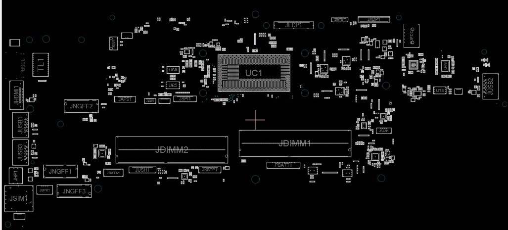
brd file anywhere in Webpage and click submit. You can Go to the link and just drag your. Board size and component placement are correct but the image on top and bottom of the board showing the traces, resist and silk are compressed to fit the board outline.

Text, traces and other stuff outside the board dimension area produce incorrect texture renderings.you launch the script ( they are allegro scripts ) Allegro launches and exports the brd file into an ascii readable intermediate format that retains all information ( netlist etc ).
#Allegro brd viewer trial
It is possible to achieve any rotation, but it takes some trial and error. essentially you make a directory, drop in the allegor brd file and 3 script files that altium supplies.
#Allegro brd viewer series
See also SPD3303X / SPD3303X-E SERIES PROGRAMMABLE DC POWER SUPPLY The changes you make are saved in your browser local storage based on the filename of the board, so that next time you load it it will have the same translations/offsets/models/boxes. Then if there are alignment issues you can move each element individually from it’s dropdown menu.

Most connector manufacturers provide a step file for their products.Īfter you click “Place” the tool will add that model to the scene for all elements with the same package. Upload a file – stp and dae formats are currently supported. Define a box – find the datasheet for your device and get the dimensions from there.Ģ. If you can’t there are two other options:ġ. “Not found” models are red-ish colored (right hand side list), once you select an element click “Manage Model” and try to find your element model in the list of available models. We’ve tried to include the most used packages, but we can’t account for every device out there, and probably your board won’t render completely the first time you load it. The tool currently has close to two hundred 3D models of different components.


 0 kommentar(er)
